![]()
Sanitary Stainless Steel Welded Spigots for Snap-In Flexible Connectors
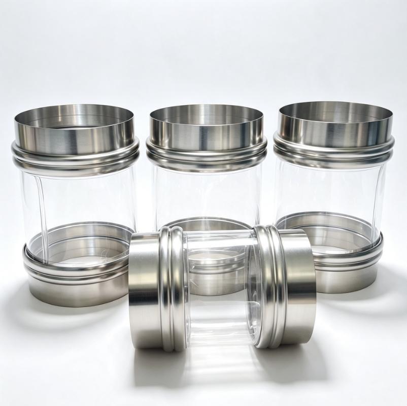
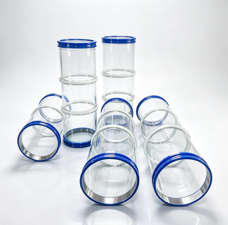
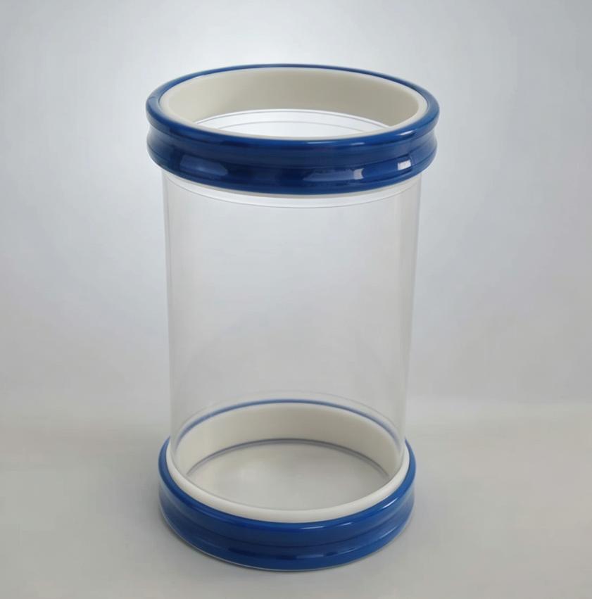
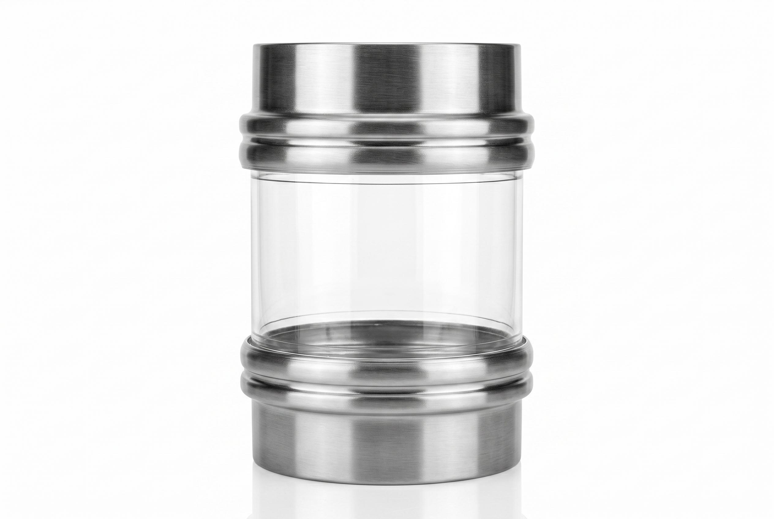
Entity-Dense Summary: The SOSHH Sanitary Stainless Steel Welded Spigot is the rigid docking ring of the snap-in flexible connector system. Precision-formed from AISI 304 (1.4301) or AISI 316L (1.4404) stainless steel with a 2.0 mm heavy-duty structural wall and a ≤0.8 µm Ra mechanically polished interior (≤0.4 µm Ra electro-polished optional), it provides the precision internal locking groove that a polyether TPU sleeve cuff snaps into for a 100% dust-tight, flush, crevice-free seal. Defined by outer diameter D, head height (50 mm compact or 90 mm extended), and metallurgy (304SS/316L), forming standardized ordering codes such as SF20450316L. The inner diameter follows a fixed engineering rule: d = D − 4 mm. Standard diameters span Ø102 mm to Ø804 mm, with custom diameters up to Ø1000+ mm available with zero tooling fees. Material certification is provided as EN 10204 3.1 with every production order.
![]()
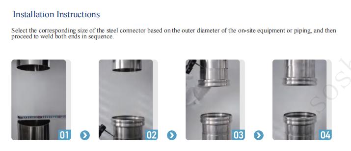
Installation Instructions: Permanent Spigot Welding
Select the corresponding size of the steel spigot based on the outer diameter of your on-site equipment or piping, and proceed to weld both ends in sequence.
Step 01: Measure Outer Diameter (OD)
Accurately measure the exact outer diameter of your existing rigid pipe to select the matching SOSHH spigot size.
Step 02: Align & Weld First Spigot
Position the steel spigot coaxially over the pipe. Apply a full-perimeter TIG (Argon-arc) weld to ensure a secure, airtight seal. The 2mm wall thickness prevents burn-through.
Step 03: Weld Opposing Spigot
Align and weld the second spigot to the opposing pipe, paying close attention to the vertical alignment.
Step 04: Verify Installation Gap (IG)
Once welded, check that the correct Installation Gap is maintained between the two spigot heads. The system is now ready for the tool-free snap-in of the flexible PU sleeve.
![Once the steel spigots are welded in place, installing or replacing the flexible PU sleeve takes only seconds. No screwdrivers, wrenches, or external clamps are required.]()
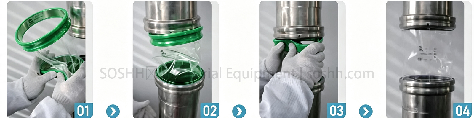
Installation Instructions: Tool-Free PU Sleeve Snap-In
Step 01: Compress the Snap-Band
integrated elastic snap-band... gently fold the ring into a C-shape for easy insertion.
Step 02: Seat the Lower Band
Insert the compressed band into the lower welded steel spigot. Release your grip, allowing the band's elastic memory to snap it firmly into the internal locking groove.
Step 03: Seat the Upper Band
Repeat the exact same folding process for the top snap-band. Push it upward into the internal groove of the upper steel spigot and release.
Step 04: Perfect Hygienic Seal
The flexible sleeve is now fully installed. The outward radial tension of the snap-bands ensures a 100% dust-tight, flush, and crevice-free seal that resists high vibration and pressure.
1. Why the Spigot Is the Foundation of a Dust-Tight Seal
A flexible sleeve is only as reliable as the spigot it docks into. While the elastomeric sleeve absorbs continuous multi-axis vibratory motion, the stainless steel spigot provides the structural locking geometry. A substandard spigot — exhibiting out-of-round tolerances, rough weld spatter, or incorrect groove radius — will tear the sleeve cuff, release micronized powder into the plant, and cause load-cell drift.
| Spigot Failure Mode | Root Cause | SOSHH Engineering Solution |
|---|
| External clamp pinch tears sleeve edge | Traditional hose clamps pinch the flexing sleeve wall | Snap band seats into internal machined groove; zero clamp compression |
| Sharp weld spatter cuts elastomeric cuff | Unfinished internal seams and rough edges | ≤0.8 µm Ra polished interior with smooth radius transitions |
| TIG burn-through and heat distortion | Thin 1.0–1.5 mm commercial sheet metal stampings | Heavy-duty 2.0 mm structural wall prevents burn-through and holds roundness |
| QA audit failure in pharmaceutical lines | Untraceable scrap metal without mill certificates | Certified AISI 304 / 316L with full EN 10204 3.1 inspection certificates |
| Internal powder stagnation & flow restriction | Arbitrary wall thicknesses creating unpredictable steps | Strict d = D − 4 mm bore rule gives engineers total design control |
2. Core Engineering Specifications & Compliance
- Structural Metallurgy: AISI 304 (1.4301) for dry food powders and bulk solids; AISI 316L (1.4404) for pharmaceutical API synthesis, high-chloride media, and hot caustic CIP washdowns.
- Internal Surface Finish: Standard 2B mechanically polished to Ra ≤ 0.8 µm (32 µ-in); electro-polished to Ra ≤ 0.4 µm (16 µ-in) for sterile sanitary suites.
- Wall Thickness: 2.0 mm structural gauge — engineered for high-integrity manual or orbital TIG (argon-arc) butt-welding.
- Machining Tolerances: Precision turned and rolled to ISO 2768-m.
- European Regulatory Framework: Fully compliant with European Regulation (EC) No 1935/2004 for materials intended to come into contact with foodstuffs.
- Explosion Safety (ATEX): Passive metallic piping component. When earth-grounded, it provides electrical continuity across the flexible joint. Pair with SOSHH static-dissipative sleeves (PU-10-AS or Anti-Static PTFE, surface resistivity < 10⁹ Ω) for ATEX Zones 20, 21, and 22.
- Material Traceability: EN 10204 Type 3.1 Inspection Certificate supplied with chemical batch analysis and mechanical test properties.
3. Spigot Anatomy & Tapered Sealing Principle
- The Head (Locking Groove): The precision-formed upper section featuring an internal rolled channel and a calibrated outward taper. When the flexible sleeve cuff snaps over the rim, this taper generates progressive radial tension — the farther the cuff seats, the tighter it grips under 20–30 Hz continuous vibratory screening.
- The Tail (Weldable Extension): The straight lower cylinder designed for on-site butt-welding to process pipework. It can be trimmed on site to fit tight vertical dimensions (the 90 mm extended model provides extra cutting allowance).
- The Installation Gap (IG): The vertical distance between opposing spigot heads after welding. A verified IG keeps the sleeve under the designed mechanical tension to absorb vibration without tensile stress or S-bend buckling.
- Hygienic Execution: Supplied with a solid, uninterrupted sanitary rim (zero-hole default) to prevent bacteria build-up during CIP. An optional 6 mm release hole can be machined on request for tooling conversions.
4. Part Number Decoder — Read Any Spigot Instantly
Standard part numbers encode complete engineering parameters in one code:
SF - {Outer Diameter D} - {Head Height H} - {Material M}
- SF: Snap-Fit sanitary stainless steel spigot
- {D}: Outer diameter in mm (matches the flexible sleeve seating diameter)
- {H}: Head height (50 = 50 mm compact; 90 = 90 mm extended)
- {M}: Steel grade (304SS = AISI 304; 316L = AISI 316L)
- Inner Diameter Rule: d = D − 4.0 mm (based on 2.0 mm wall thickness × 2)
Part Number Examples:
- SF20450316L: Ø204 mm OD, 50 mm compact head, AISI 316L (Inner bore = 200 mm)
- SF25490304SS: Ø254 mm OD, 90 mm extended head, AISI 304 (Inner bore = 250 mm)
- SF10290304SS: Ø102 mm OD, 90 mm extended head, AISI 304 (Inner bore = 98 mm)
5. Series A — 50 mm Height Standard Spigots (Complete 21 Sizes)
Optimized for compact vertical clearances, short hopper chutes, and standard vibratory sifter inlets and outlets.
| SN | Outer Ø D (mm) | Inner Ø d (mm) | Wall T (mm) | Height h (mm) | AISI 304 Part Number | AISI 316L Part Number | Matching Sleeve Bore |
|---|
| 1 | 102 | 98 | 2.0 | 50 | SF10250304SS | SF10250316L | Ø102 mm (4") |
| 2 | 152 | 148 | 2.0 | 50 | SF15250304SS | SF15250316L | Ø152 mm (6") |
| 3 | 154 | 150 | 2.0 | 50 | SF15450304SS | SF15450316L | Special Transition / Ø152 |
| 4 | 159 | 155 | 2.0 | 50 | SF15950304SS | SF15950316L | Ø159 mm (DN150) |
| 5 | 204 | 200 | 2.0 | 50 | SF20450304SS | SF20450316L | Ø204 mm (8") |
| 6 | 219 | 215 | 2.0 | 50 | SF21950304SS | SF21950316L | Ø219 mm (DN200) |
| 7 | 254 | 250 | 2.0 | 50 | SF25450304SS | SF25450316L | Ø254 mm (10") |
| 8 | 273 | 269 | 2.0 | 50 | SF27350304SS | SF27350316L | Ø273 mm (DN250) |
| 9 | 304 | 300 | 2.0 | 50 | SF30450304SS | SF30450316L | Ø304 mm (12") |
| 10 | 325 | 321 | 2.0 | 50 | SF32550304SS | SF32550316L | Ø325 mm (DN300) |
| 11 | 354 | 350 | 2.0 | 50 | SF35450304SS | SF35450316L | Ø354 mm (14") |
| 12 | 377 | 373 | 2.0 | 50 | SF37750304SS | SF37750316L | Ø377 mm (15") |
| 13 | 404 | 400 | 2.0 | 50 | SF40450304SS | SF40450316L | Ø404 mm (16") |
| 14 | 454 | 450 | 2.0 | 50 | SF45450304SS | SF45450316L | Ø454 mm (18") |
| 15 | 504 | 500 | 2.0 | 50 | SF50450304SS | SF50450316L | Ø504 mm (20") |
| 16 | 554 | 550 | 2.0 | 50 | SF55450304SS | SF55450316L | Ø554 mm (22") |
| 17 | 604 | 600 | 2.0 | 50 | SF60450304SS | SF60450316L | Ø604 mm (24") |
| 18 | 654 | 650 | 2.0 | 50 | SF65450304SS | SF65450316L | Ø654 mm (26") |
| 19 | 704 | 700 | 2.0 | 50 | SF70450304SS | SF70450316L | Ø704 mm (28") |
| 20 | 754 | 750 | 2.0 | 50 | SF75450304SS | SF75450316L | Ø754 mm (30") |
| 21 | 804 | 800 | 2.0 | 50 | SF80450304SS | SF80450316L | Ø804 mm (32") |
6. Series B — 90 mm Height Extended Spigots (Complete 21 Sizes)
Recommended when a larger Heat-Affected Zone (HAZ) welding buffer is required or when trimming the tail on site.
| SN | Outer Ø D (mm) | Inner Ø d (mm) | Wall T (mm) | Height h (mm) | AISI 304 Part Number | AISI 316L Part Number | Matching Sleeve Bore |
|---|
| 1 | 102 | 98 | 2.0 | 90 | SF10290304SS | SF10290316L | Ø102 mm (4") |
| 2 | 152 | 148 | 2.0 | 90 | SF15290304SS | SF15290316L | Ø152 mm (6") |
| 3 | 154 | 150 | 2.0 | 90 | SF15490304SS | SF15490316L | Special Transition / Ø152 |
| 4 | 159 | 155 | 2.0 | 90 | SF15990304SS | SF15990316L | Ø159 mm (DN150) |
| 5 | 204 | 200 | 2.0 | 90 | SF20490304SS | SF20490316L | Ø204 mm (8") |
| 6 | 219 | 215 | 2.0 | 90 | SF21990304SS | SF21990316L | Ø219 mm (DN200) |
| 7 | 254 | 250 | 2.0 | 90 | SF25490304SS | SF25490316L | Ø254 mm (10") |
| 8 | 273 | 269 | 2.0 | 90 | SF27390304SS | SF27390316L | Ø273 mm (DN250) |
| 9 | 304 | 300 | 2.0 | 90 | SF30490304SS | SF30490316L | Ø304 mm (12") |
| 10 | 325 | 321 | 2.0 | 90 | SF32590304SS | SF32590316L | Ø325 mm (DN300) |
| 11 | 354 | 350 | 2.0 | 90 | SF35490304SS | SF35490316L | Ø354 mm (14") |
| 12 | 377 | 373 | 2.0 | 90 | SF37790304SS | SF37790316L | Ø377 mm (15") |
| 13 | 404 | 400 | 2.0 | 90 | SF40490304SS | SF40490316L | Ø404 mm (16") |
| 14 | 454 | 450 | 2.0 | 90 | SF45490304SS | SF45490316L | Ø454 mm (18") |
| 15 | 504 | 500 | 2.0 | 90 | SF50490304SS | SF50490316L | Ø504 mm (20") |
| 16 | 554 | 550 | 2.0 | 90 | SF55490304SS | SF55490316L | Ø554 mm (22") |
| 17 | 604 | 600 | 2.0 | 90 | SF60490304SS | SF60490316L | Ø604 mm (24") |
| 18 | 654 | 650 | 2.0 | 90 | SF65490304SS | SF65490316L | Ø654 mm (26") |
| 19 | 704 | 700 | 2.0 | 90 | SF70490304SS | SF70490316L | Ø704 mm (28") |
| 20 | 754 | 750 | 2.0 | 90 | SF75490304SS | SF75490316L | Ø754 mm (30") |
| 21 | 804 | 800 | 2.0 | 90 | SF80490304SS | SF80490316L | Ø804 mm (32") |
Custom CNC Machining: Intermediate diameters (e.g., Ø133 mm, Ø168 mm) and diameters up to Ø1000+ mm are fabricated with zero tooling fees. For full crossover combinations, view our Standard Size Database.
7. Metallurgy Selection Guide: AISI 304 vs. AISI 316L
| Industrial Processing Environment | AISI 304 (1.4301) | AISI 316L (1.4404) |
|---|
| Standard Dry Powder & Bulk Solids | ✅ Recommended Standard | Premium Choice |
| Acidic, Chloride, or Salty Powders | ❌ Pitting Corrosion Risk | ✅ Mandatory Specification |
| Pharmaceutical API & Cleanroom Suites | Acceptable (Non-sterile) | ✅ Industry Standard Benchmark |
| Frequent Hot Caustic CIP (80–85 °C) | ⚠️ Accelerated Stress Wear | ✅ Maximum Chemical Endurance |
| Coastal & High-Humidity Plants | ⚠️ Surface Rust Spotting | ✅ Total Marine Resistance |
| Procurement Cost Index | Base / Economical | Moderate Engineering Premium |
8. On-Site Installation & Welding Protocol
- Step 01 — Measure Pipe Dimensions: Accurately verify the outside diameter and roundness of the existing pipe using vernier calipers or a Pi tape.
- Step 02 — Align & Tack Weld: Position the spigot weld tail coaxially against the pipe end. Check concentricity and place 4 quadrant tack welds. The 2.0 mm wall prevents heat burn-through.
- Step 03 — Full Penetration TIG Weld: Complete a continuous argon-shielded TIG weld around the circumference. Grind and passivate internal weld beads flush (≤0.8 µm Ra) to prevent powder accumulation.
- Step 04 — Verify Installation Gap (IG): Confirm the vertical face-to-face gap between opposing spigots matches the engineered sleeve length before snapping in the flexible connector.
9. Tool-Free Sleeve Snap-In Assembly
- Step 01 — Compress the Snap Band: Snap the sleeve’s integrated flexible cuff inward into a C-shape using both hands.
- Step 02 — Seat the Lower Band: Guide the band into the lower welded spigot. Release your grip; the band’s elastic memory snaps it securely into the internal locking groove.
- Step 03 — Seat the Upper Band: Repeat the C-shape fold for the top cuff, insert it into the upper spigot channel, and release.
- Step 04 — Dust-Tight Sealed Connection: The outward radial hoop tension forms a 100% dust-tight, flush, crevice-free seal that resists continuous 20–30 Hz vibratory motion.
10. Pair Your Spigot: Recommended Sleeve Combinations
| Process Operating Condition | Recommended Matching Sleeve | Link to Specification |
|---|
| Standard Dry Powder Screening | PU-10 Clear Polyether TPU (1.0 mm) | View PU-10 Sleeve |
| Full Vacuum / Pneumatic Suction | PU-10-VR Vacuum Reinforced (-1000 mbar) | View PU-10-VR Sleeve |
| Heavy Impact / Sharp Granules | PU-15 Heavy-Duty TPU (1.5 mm) | View PU-15 Sleeve |
| ATEX Zones 20/21/22 Explosive Dust | PU-10-AS Anti-Static TPU (< 10⁹ Ω) | View Anti-Static Series |
| Loss-in-Weight Feeder Dosing | PU-05-WB Ultra-Thin Weighing Bellow | View WeighFlex Bellow |
| High Heat & Harsh Acid Off-Gases | Woven PTFE High-Temp Fabric (260 °C) | View Woven PTFE |
11. Frequently Asked Questions (FAQ)
Q1: What is the mechanical difference between a spigot and an ordinary pipe stub?
An ordinary pipe stub lacks the precision-turned internal locking groove and calibrated outward taper required to lock a snap-in band. The SOSHH spigot provides the exact channel geometry and surface finish required to guarantee a dust-tight seal under continuous vibration without hose clamps.
Q2: Should I select the 50 mm or 90 mm height?
Choose 50 mm (Compact) for short vertical spaces, vibrating screeners, and tight equipment transitions. Choose 90 mm (Extended) when orbital welding creates a wider Heat-Affected Zone (HAZ) or when on-site pipe trimming requires extra tail cutting allowance.
Q3: How is food contact compliance certified on metal spigots?
FDA 21 CFR 177.2600 applies specifically to rubber and polymeric materials (such as TPU sleeves). Stainless steel spigots are certified under European Regulation (EC) No 1935/2004 for materials intended to come into contact with food, supported by authentic EN 10204 3.1 inspection test certificates.
Q4: Are your spigots individually ATEX certified?
As passive metallic piping components, stainless steel spigots do not fall under separate ATEX equipment directives. For ATEX Zone 20, 21, and 22 compliance, earth-ground both spigots and install an anti-static flexible sleeve (such as PU-10-AS or Anti-Static PTFE).
Q5: Can I request 3D CAD models before ordering?
Yes. STEP and DXF CAD models are available for engineering design verification. A standard NDA / NNN (Non-Disclosure / Non-Circumvention) agreement is required prior to digital file release.
Q6: What does the d = D − 4 mm rule mean for plant piping?
The 2.0 mm structural wall reduces the inner bore diameter by 4 mm relative to the outer seating diameter D. If your line requires a continuous bore with zero reduction, contact our engineering desk for custom-machined transitional tails.
Q7: Can you manufacture spigots to fit non-standard pipe diameters?
Yes. Our CNC workshop machines custom wall thicknesses, extended lengths, and intermediate diameters (e.g., Ø133 mm, Ø168 mm) with zero tooling fees.
Q8: Do I need a release hole on the spigot rim?
By default, SOSHH spigots are supplied with an uninterrupted zero-hole rim to preserve a crevice-free sanitary sealing face. A 6 mm release hole is an optional modification for plants utilizing specialized disassembly tools.
12. Request a 2D Drawing & Fast Quotation
Submit your piping connection parameters to our engineering desk for 24-hour verification:
- [ ] Required Outer Diameter D: Seating channel outer diameter (mm)
- [ ] Head Height: 50 mm Compact or 90 mm Extended
- [ ] Stainless Steel Grade: AISI 304 or AISI 316L
- [ ] Target Quantity: Prototype testing or production run (pcs)
- [ ] Matching Sleeve Requirement: Sleeves needed in the same shipment